When working with sheet metal parts in SOLIDWORKS, designers often start with an existing solid model and convert it into a sheet metal component to enable flattening, bend calculations, and manufacturing documentation.
Two commands commonly used for this purpose are Convert to Sheet Metal and Insert Bends. At first glance, both tools appear to perform similar functions—they transform a solid part into a sheet metal model. However, the underlying logic and intended use cases are quite different.
Understanding when to use each command is essential for building robust sheet metal models and avoiding problems later in the design process.
The model below are designed using solid modelling features.
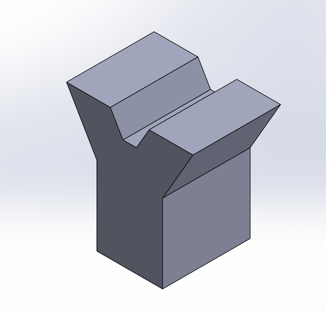
Convert to Sheet Metal
The Convert to Sheet Metal in SOLIDWORKS is relatively straightforward to use. Designers begin by defining the key sheet metal parameters, either by selecting a gauge table or by manually specifying values such as material thickness and bend radius. Additional options can also be configured at this stage, including the default corner type, bend allowance, and auto relief settings.
Once these parameters are defined, the next step is to select the fixed face and the edges that will become bends. The fixed face acts as the reference surface, meaning all other faces will bend relative to it. The selected bend edges determine where the bends will occur in the sheet metal model.
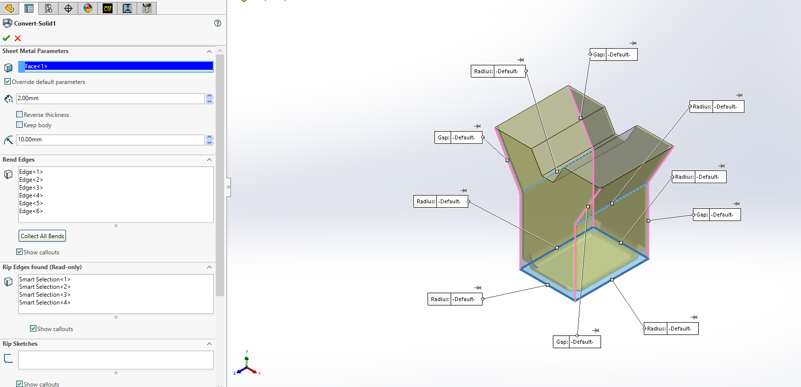
In cases where the selected edges require a separation between faces to allow proper unfolding, SOLIDWORKS will automatically generate the necessary rips. One advantage of this workflow is its flexibility—if the wrong edges are selected or manufacturing requirements change, the feature can simply be edited and the bend edges redefined without needing to remodel the entire part.
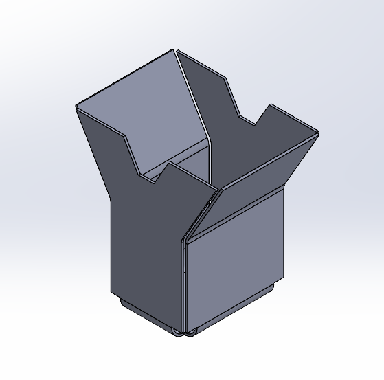
Insert Bend
The Insert Bends technique extends a solid body by first shelling it to establish a uniform wall thickness, preparing it for sheet metal conversion.
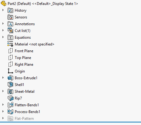
Unlike the Convert to Sheet Metal method, where bend edges are selected and rips are automatically created, Insert Bends requires specifying the edges to rip, and the software generates the corresponding bends automatically.
Within the Insert Bends PropertyManager, the Fixed Face, Bend Radius, Bend Allowance, and Auto Relief are defined.
The sheet metal thickness is derived from the shell thickness.
Edges designated for ripping are then assigned a rip gap size and direction, with the Change Direction button available for adjustments.
The yellow arrows in the interface indicate the direction of the rip, which can be set to “both” or a single side as needed.
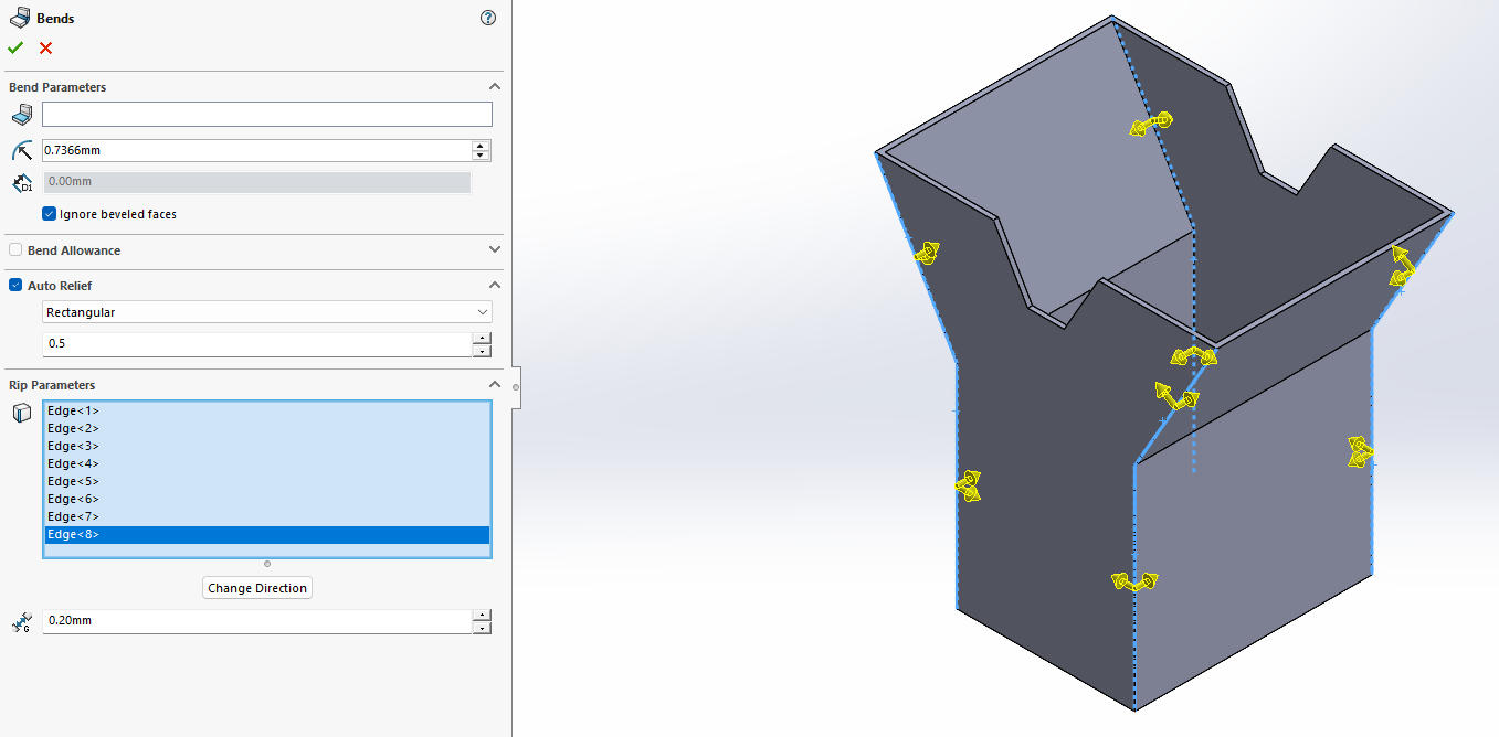
This workflow provides precise control over rip placement and is particularly effective for parts with complex geometries that have already been prepared with a uniform wall thickness.
Leveraging the Keep Body Option
Both methods provide a straightforward workflow for converting a solid body into a sheet metal part. The Convert to Sheet Metal command offers one distinct advantage through the Keep Body option, available in the Sheet Metal Parameters window. This feature preserves the original solid body after the sheet metal conversion.
The ability to retain the original body facilitates the creation of multi-body sheet metal parts. For example, if the entire sheet metal hopper cannot be fabricated from a single 250mm by 150mm blank, it may need to be constructed from multiple pieces that are later welded together.
By keeping the original solid body, additional sheet metal bodies can be defined efficiently, maintaining geometric consistency and simplifying the workflow for complex assemblies.