A Half Section View shows one half of a view as a section, and the other half as a normal exterior view. It is commonly used for symmetrical parts (and some symmetrical assemblies) to clearly show internal features without fully sectioning the entire view.
Typical use cases include shafts, bushings, pulleys, housings, bearings, and turned parts, where the model has a clear center axis.
When to use a Half Section View
Use a Half Section View when you want:
-
Internal details on one side, such as bores, steps, ribs, counterbores
-
External profile on the other side, such as fillets, outer diameter, grooves
-
A cleaner drawing compared to a full section, especially for symmetric geometry
Avoid using a half section when:
-
The part is not symmetric about the intended centerline
-
The view is cluttered, and a full section or broken out section communicates better
-
The assembly has many internal components that become confusing when half sectioned
Method To Create a Half Section View using the Section View command
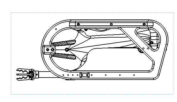
Step 1, Select the parent view
-
Click the drawing view you want to section, for example the Right view
-
Make sure you can see the centerline that represents the axis of symmetry
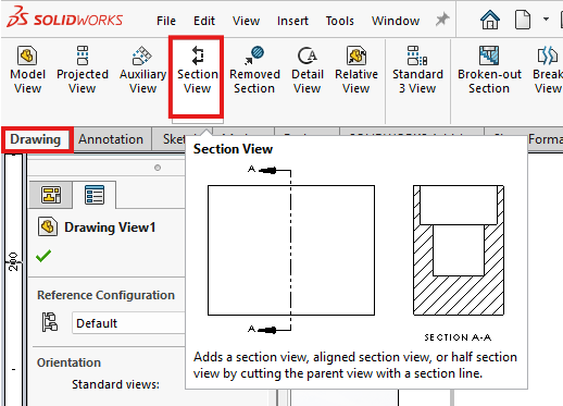
Step 2, Start Section View
-
Go to Drawing or View Layout tab
-
Click Section View
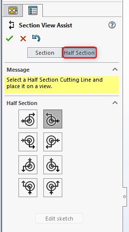
Step 3, Choose the Half Section option
In the Section View PropertyManager:
-
Look for a section type option such as Half Section
-
Select Half Section
-
Confirm the direction of the section, flip direction if the wrong half is sectioned
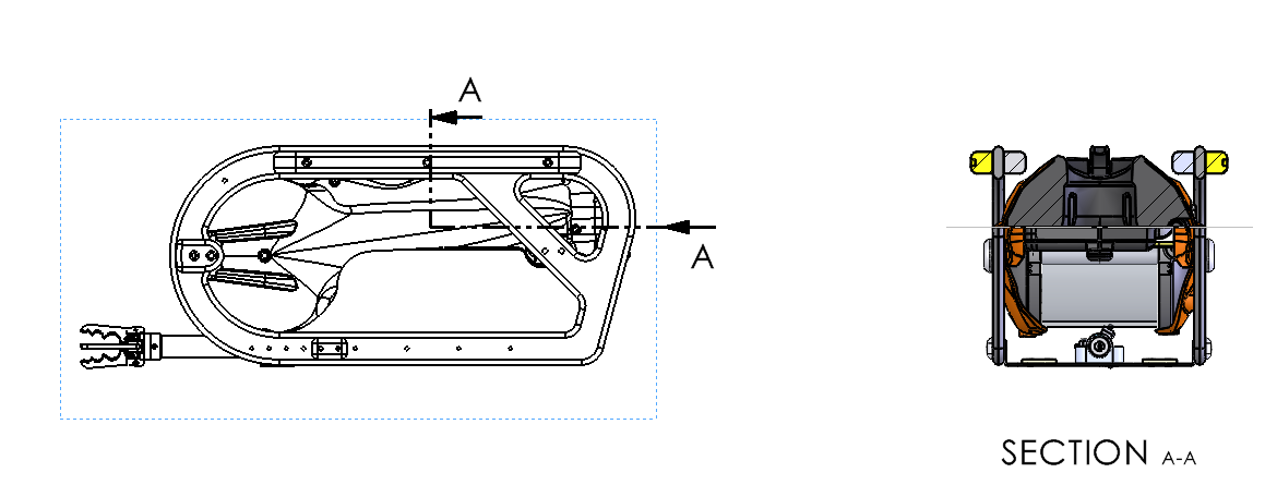
What you should see:
-
One half of the resulting view shows hatch lines on cut material
-
The other half remains a standard view without hatching
Step 4, Place the section view
-
Move your cursor to position the new view
-
Click to place it
-
SOLIDWORKS will label it, for example Section A A, depending on your settings